2. The Matrix Circuit
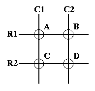
Keyboards use a matrix with the rows and columns made up of wires. Each key acts like a switch. When a key is pressed, a column wire makes contact with a row wire and completes a circuit. The keyboard controller detects this closed circuit and registers it as a key press. Here is a simple keyboard matrix:
Figure 1. Conceptual Matrix Circuit

This keyboard only has 4 keys: A, B, C, and D. Each key has a unique grid location, much like points on a graph. Key A is at node C1R1, key B is at node C2R1, key C is at node C1R2, and key D is at node C2R2. In reality this is pretty useless which is why real keyboards use many more rows and columns. However, I want to keep it simple.
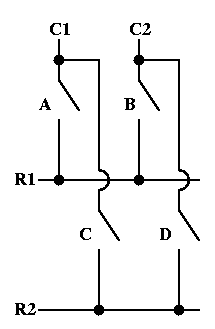
The electronic circuit for this matrix looks something (not exactly) like this:
Figure 2. Switch Open
