4. Single Key Presses
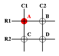
Now, let's say the the A key is pressed. The matrix will look like this:
Figure 5. The A Key is Pressed

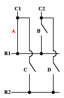
Key A corresponds to node C1R1. By going back to the circuit, we can see how C1R1 is detected. First, here is the circuit with switch A closed:
Figure 6. The A Switch is Closed

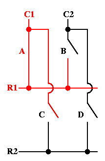
Walking through the scanning procedure again, the controller activates column C1 and detects which rows are activated:
Figure 7. Row 1 is Activated

This time, row R1 is activated. So the controller now knows that node C1R1 is pressed. Since C1R1 corresponds to the A key, the controller knows that the A key is pressed.
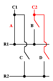
When the controller activates column C2, neither row R1 nor R2 are activated. Both switches B and D are open:
Figure 8. Neither Row is Activated

When the A key is released, the circuit goes back to the original, and the controller detects the node C1R1 is no longer activated.