Transistor Circuit Analysis
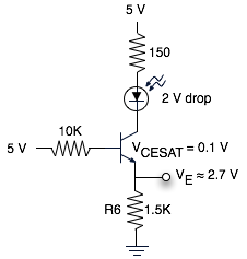
Not one to let sleeping dogs lie, I wanted to know why the MOSI pin was only being pulled down to 2.8 V with the 1.5K Ohm resistor on R6 in my previous post. The resulting schematic is this fairly simple transistor circuit:
Seeing schematics with transistors in them brings back a flood of memories to my college days when I was taking EE classes and I used to know how to do this stuff in my sleep. Unfortunately, that was about 15 years ago, and now a schematic like that looks like gibberish. It was bugging me that I used to be able to figure this stuff out, so I pulled out my old textbooks. Those were nearly as incomprehensible as the schematic, unfortunately.
Luckily we have teh internets these days, and I found instructions on transistor circuit analysis that I could actually understand on the website for EECS 312 at the University of Kansas. Kudos to Prof. Stiles for making this understandable. This transistor is in saturation mode, and I calculated the emitter voltage to be about 2.7 V. I measured the voltage drop to be 2.72 V with the scope, which you can see on the right side of the scope’s screen in this picture. It’s nice when theory and practice align. It’s even nicer when I don’t have to show my work.