More USBtinyISP Fixes
In my post about the STK500 and USBtinyISP, I linked to a thread about how to fix a design error in version 2.0 of the USBtinyISP. It mentioned shorting out R6 and R7 to fix communications errors during programming. I did this, but I was still having trouble programming over ISP while I had the LEDs connected. bbum mentioned that he was able to program with LEDs attached, so I suspected something about my setup. At first, I thought it was specific to the STK500, but it turns out the problem was with the USBtinyISP itself. The STK500 just tweaked the right conditions to expose it.
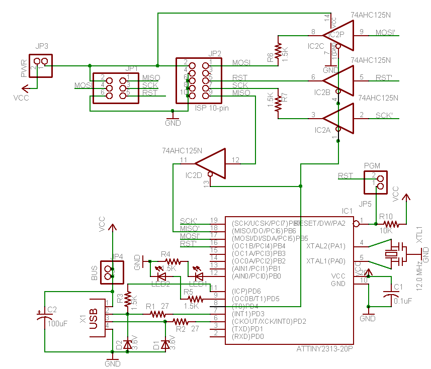
The thread mentions shorting out R6 and R7, but that was in reference to the v2.0 schematic where R6 and R7 are in series with the MOSI and SCK signals. Unfortunately, the v2.0 circuit board has R6 and R4 mislabeled on the silkscreen: they’re swapped! So if you followed the instructions and shorted out what’s labeled as R6, you really shorted out R4. This not only doesn’t fix the MOSI signal, it also connects the red LED up to an I/O port without a current limiting resistor. Now you’ve got two problems.
The proper fix is to short out what’s labeled on the PCB as R4 and R7. Once I did this, it fixed my avrdude communications errors with LEDs connected. If you did short out what’s labeled as R6, I suggest you put a 1.5K Ohm resistor back to properly limit current through the red LED. Hopefully ladyada will update the official instructions about this, and even build a v2.1 version of the PCB without the 1.5K resistors on MOSI and SCK.
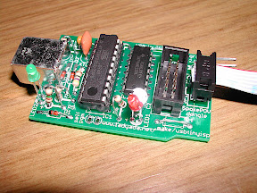
Here’s a picture of the final result. Read on for details and more pictures about the problem.
Debugging Hardware
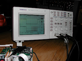
One of the best hardware debugging tools is an oscilloscope. Other tools include logic analyzers and higher-level bus analyzers (such as a USB bus analyzer), but if you’re only going to have one tool, I’d say make it a scope. Often hardware design errors result in off voltages or voltage glitches that can only be seen with a scope. I bought a nice digital storage oscilloscope for a client project I worked on a few years ago, and it paid for itself in a short time.
The first thing I did was hook up the scope to the signals used by ISP. ISP works by pulling the RESET signal low, and then running a simple serial protocol over MOSI and MISO as data signals and the clock on SCK, pins PB3, PB4 and PB5 respectively on a ATmega168. I checked each of these signals with the scope, and noticed that MOSI was only getting pulled down to between 2.80 V to 2.88 V. In digital electronics, you’re dealing with 1s and 0s. In a 5 V system, that means all signal voltages should be very near either 5 V or 0 V. Seeing an in-between value like 2.80 V is one of those telltale signs that you need to investigate further (the top signal is RESET):

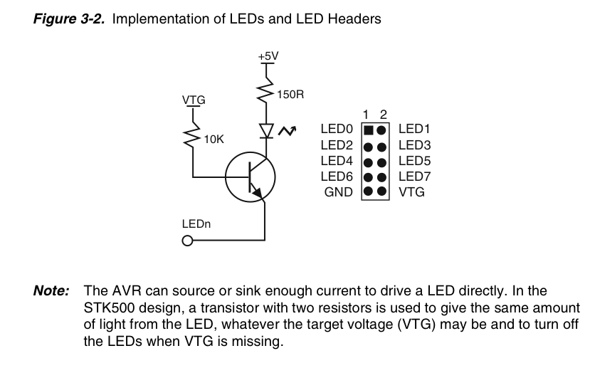
I thought maybe MOSI pin (PB3) had different electrical characteristics on the microcontroller than the other PORTB pins. Reading over the data sheet didn’t corroborate this, so that wasn’t the issue. Then I looked at the STK500’s LED schematics. After all, my STK500 was showing the issue, while others weren’t seeing it. Maybe the LED hooked up to PB3 was somehow different from SCK (PB5). But nope, all LEDs were hooked up the same way, so that wasn’t the issue, either. This pretty much ruled out everything on my board, and meant it was time to check the USBtinyISP.
When I went to measure the voltage on the short that was labeled as R6 during ISP, I noticed that the scope wasn’t registering anything at all. This was odd, as I was certainly registering something on PB3. And PB3, as MOSI, was supposed to be hooked up through R6 on the USBtinyISP, according to the schematic. After following the PCB traces to and from R6, I noticed it wasn’t hooked up to MOSI at all! Nope, it was hooked up to the red LED. But that’s supposed to be R4. So what’s the resistor on the R4 label hooked up to, then? Following the traces should this as the series resistor for MOSI. Sure enough, measuring the voltage on the labeled R4 matched up with PB3.
Identifying the Problem
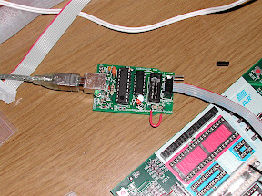
Since I left a 1.5K Ohm resistor in R4, that explained why MOSI only got pulled down to 2.80 V during ISP. The resistor was messing it all up! For more information on why this is a problem, see my next post. Of course, this all made sense, since this was the defect that shorting out R6 and R7 was supposed to fix in the first place. But because of the silkscreen mislabeling, I shorted out the wrong resistor. I hacked up a fix to test my theory by putting a wire jumper across R4:
This time, when I ran avrdude and measured MOSI, it dropped down to near 0 V, just like it should. You can also see the serial data being transferred, too:
So, just to confirm that the silkscreen was indeed mislabeled, I re-posted on the thread. After all, no one else had mentioned this issue before, so maybe I was just hallucinating. Well, ladayada herself confirmed the error.
A Hidden Problem
As to why some people see the error and some don’t, it’s most likely a matter of differences in hardware. The MOSI pin was hooked up to an LED on the STK500, which resulted in a logic 0 being sent as 2.80 V. Unfortunately, this is not close enough to 0 V to being interpreted as a logic 0. It’s possible that MOSI could get pulled down low enough to be interpreted as a logic 0 on different hardware, in which case things would appear to work. Of course, the problem is still there, waiting to strike at just the right time.
In summary: if you’re building a USBtinyISP v2.0, short out R4 and R7 as labeled on the PCB. Oh, and buy an oscilloscope, if you can afford one.